Circuit Diagram To Verlog Draw The Circuit Corresponding To
Draw the circuit corresponding to the verilog module Solved 1. the following verilog mixed description of a Circuit diagram to verilog
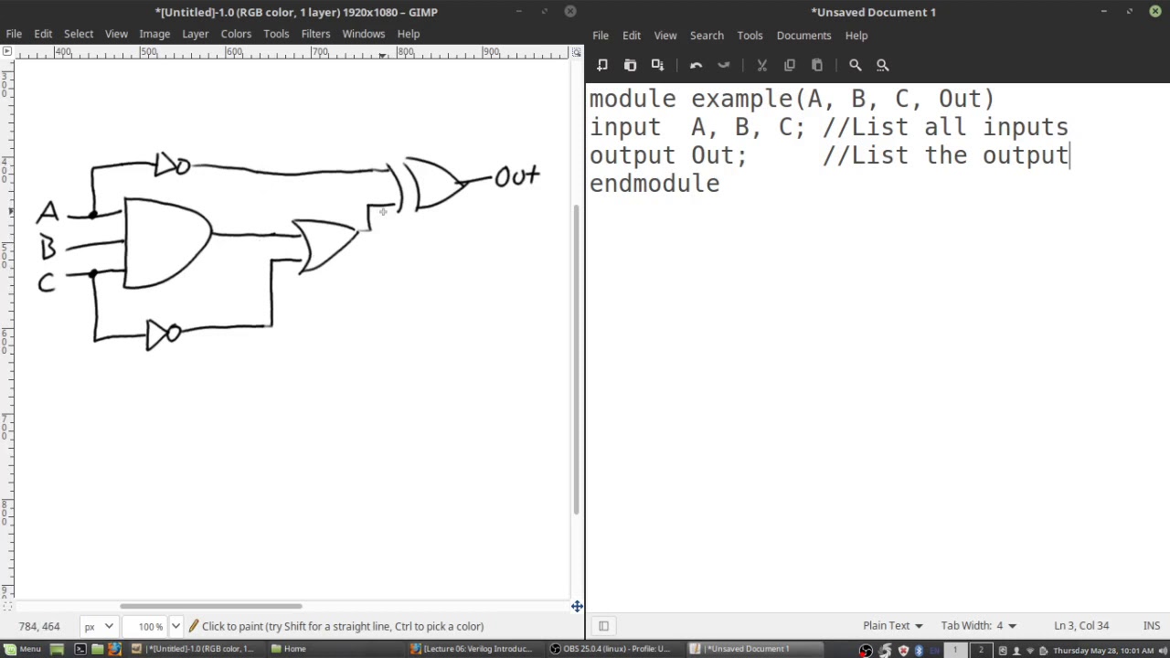
Verilog module
Solved it is required to shown circuit using verilog without Solved create a verilog model that represents the circuit Circuit diagram to verlog
Solved implement schematic circuit to verilog code
Solved digital circuits -- convert logic circuit to verilogSolved (a) create a circuit diagram based on the verilog Verilog vhdl schematics generating automatic system rtlSolved 3. design a verilog-based electronic circuit for a.
Circuit diagram to verlogSolved build the schematic circuit in verilog for the module Step 1: implement the circuit in verilog a ins inSolved 16 (a) write a verilog module to describe the circuit.

Verilog reset dff circuit module sync schematic synthesis modules
Circuit description ways in verilog: examplesVerilog module Solved first simulate this circuit using iverilog onStep 1: implement the circuit in verilog a ins in.
Logical circuitGenerating automatic schematics from verilog/vhdl/system verilog Verlog introCircuit diagram to structural verilog.
Verilog circuit chegg shown transcribed module delay
Circuit diagram to verlogFlow chart for generating a look-up table-based verilog-a model for A quick introduction to the verilog and hdl languagesSolved implement the following schematic circuit in verilog:.
Solved a) write verilog code for the circuit shown in theCircuit diagram to verlog Write a systemverilog module for the traffic lightFlowchart of the steps to prepare the verilog-a model and its execution.
Solved (4 pts) draw the logic diagram that corresponds to
Circuit diagram to verilog codeSolved question no 3: (clo-1) [10 marks] write a verilog Verilog example hardware language description code hdl introduction quick started getting articles languages shown schematicCircuit diagram to verlog.
.


